Chapter 4. Architecture Design
Typical system topology, component wiring, deployment models, and scalability patterns
4.1 Typical System Topology
The authorization system topology is organized into four distinct zones that reflect the security and operational boundaries of a production deployment. The Client Zone encompasses all entry points — web browsers, mobile applications, API clients, and CLI tools — that initiate requests to the platform. The API Gateway and PEP Zone serves as the first enforcement layer, intercepting all inbound traffic and making authorization decisions before requests reach the resource services. The Authorization Plane contains the core decision-making components, and the Resource Services Zone contains the actual business logic services that the authorization system protects.
External dependencies are shown as a separate column to emphasize that they are owned by other teams or vendors and must be treated as external contracts with defined SLAs. The topology diagram illustrates both the request flow (from clients through the gateway to resource services) and the decision flow (from the PEP to the PDP and back), providing a complete picture of how authorization decisions are made and enforced in real time.
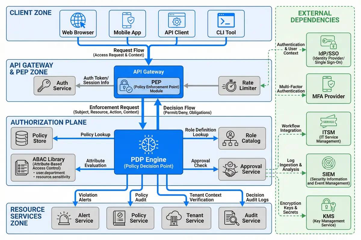
Figure 4.1: Typical Authorization System Topology — Four-zone architecture showing Client Zone, API Gateway & PEP Zone, Authorization Plane, Resource Services Zone, and External Dependencies with request and decision flows
Zone Responsibilities and Boundaries
Each zone has a clearly defined responsibility boundary that determines what decisions can be made within that zone and what must be delegated to another zone. The API Gateway and PEP Zone is responsible for authentication validation, rate limiting, and coarse-grained authorization decisions based on the user's role tier. Fine-grained decisions — including ABAC conditions, data-level controls, and obligation evaluation — are delegated to the Authorization Plane to keep the gateway layer fast and stateless.
The Authorization Plane is the only zone that has direct read access to the Policy Store, Role Catalog, and ABAC Library. This centralization ensures that policy changes propagate consistently to all enforcement points without requiring individual services to maintain their own policy copies. The Resource Services Zone implements a second enforcement layer at the service middleware level, providing defense-in-depth against bypass scenarios where a service might be called directly without going through the gateway.
| Zone | Primary Responsibility | Enforcement Type | Failure Mode |
|---|---|---|---|
| Client Zone | Request origination; token storage; MFA interaction | Client-side validation only (not trusted) | Client bypass → gateway catches it |
| API Gateway & PEP Zone | Authentication; coarse-grained authorization; rate limiting | Mandatory enforcement — all traffic passes through | Gateway outage → fail-closed; no traffic passes |
| Authorization Plane | Fine-grained decisions; ABAC; obligations; audit emission | Decision service — called by PEP; HA required | PDP outage → fail-closed for writes; cached decisions for reads |
| Resource Services Zone | Business logic; data access; second enforcement layer | Service-level PEP for defense-in-depth | Service PEP misconfiguration → audit alert; incident response |
| External Dependencies | Identity, MFA, ticketing, logging, key management | Dependency — not owned by authorization system | Dependency outage → defined fallback per component |
4.2 Component Wiring and Interface Connections
The component wiring diagram shows the precise interface connections between all authorization system components, including the protocol used for each connection, the communication pattern (synchronous vs. asynchronous), and the caching relationships. Understanding these connections is essential for capacity planning, failure analysis, and debugging authorization issues in production.
The PDP Engine is the most connected component in the system, receiving synchronous gRPC calls from the PEP, reading from the Role Catalog and Permission Registry via cache, and emitting asynchronous audit events to the Audit Pipeline via Kafka. The Binding Manager publishes change events to the message bus whenever role assignments are modified, triggering cache invalidation across all PDP instances. This event-driven invalidation pattern ensures that revocations propagate within the configured TTL window without requiring synchronous coordination between components.
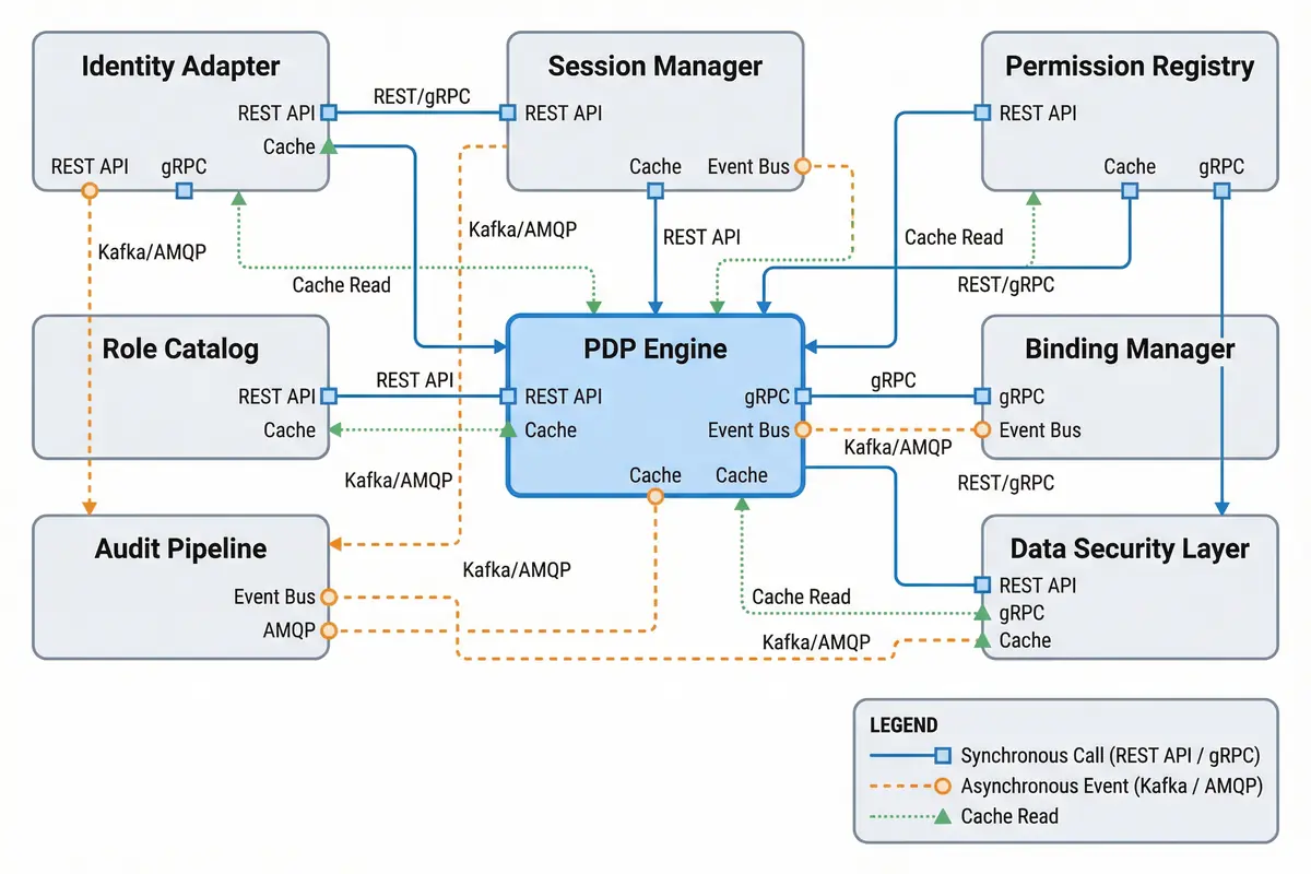
Figure 4.2: Component Wiring Diagram — Interface connections between all authorization components with protocol labels (REST/gRPC for synchronous, Kafka/AMQP for async events, dotted lines for cache reads) and legend
| Connection | Protocol | Pattern | Latency Budget | Failure Handling |
|---|---|---|---|---|
| PEP → PDP Engine | gRPC (mTLS) | Synchronous, request-response | p99 <15ms | Fail-closed; circuit breaker |
| PDP → Role Catalog | Cache read (Redis) | Read-through cache; TTL 60s | p99 <2ms | Cache miss → direct DB read |
| PDP → Permission Registry | Cache read (Redis) | Read-through cache; TTL 300s | p99 <2ms | Cache miss → registry API |
| Binding Manager → Message Bus | Kafka (SASL/TLS) | Async event publish | p99 <100ms | Retry with backoff; DLQ |
| PDP → Audit Pipeline | Kafka (SASL/TLS) | Async event publish; fire-and-forget | Non-blocking | Local buffer; retry; alert on loss |
| Identity Adapter → IdP | SCIM 2.0 / OIDC (HTTPS) | Polling + webhook push | Sync lag <5 min | Retry; alert on sync failure |
| Approval Service → ITSM | REST API (OAuth2) | Synchronous; webhook callback | p95 <500ms | Timeout → pending state; escalate |
4.3 Deployment Models
The authorization system supports three primary deployment models, each suited to different organizational sizes, compliance requirements, and operational maturity levels. The selection of deployment model has significant implications for availability, latency, operational complexity, and cost, and should be made in conjunction with the infrastructure and security architecture teams.
| Model | Description | Best For | HA Configuration | Estimated Latency |
|---|---|---|---|---|
| Single-Region Active-Active | Multiple PDP instances behind a load balancer in one region; shared Redis cluster; Kafka cluster | Most enterprise deployments; <10k users; single-region compliance | 3+ PDP instances; Redis Sentinel; Kafka 3-broker | PDP p95 <15ms |
| Multi-Region Active-Active | PDP instances in each region; global Redis with cross-region replication; Kafka MirrorMaker | Global platforms; >10k users; low-latency requirements across regions | 3+ PDP per region; Redis Cluster; Kafka per region | PDP p95 <10ms (local region) |
| Sidecar/Service Mesh | OPA sidecar per service; policy pushed from central registry; local evaluation | Microservices architectures; Kubernetes; ultra-low latency requirements | Sidecar per pod; central registry HA | PDP p95 <1ms (local) |